Abstract The global expansion of electromobility is progressing rapidly. The chinese city of Shenzhen has the world’s first and largest fleet of electric buses with more than 16,000 buses. A gigantic charging infrastructure for 5805 electric buses was established to cope with this. It reaches peak loads of 464.4 megawatts which is an enormous challenge to the grid. The use of a smart load management to avoid peak loads is indispensable. In combination with the Bidirectional Power Transfer (BPT), new perspectives open up and smart load management is efficiently enhanced.
The objective of this paper was the analysis and evaluation of the BPT for a smart load management for Electric Vehicles (EVs) regarding depot charging. This paper explains the relevant technologies and standards with respect to BPT. This was followed by the extension of Open Charge Point Protocol (OCPP) 2.0 for BPT, a prerequisite for the prototype implementation of the optimization algorithm including various strategies.
The results reveal that load management for depot charging profits substantially from BPT and that optimized planning in advance is a key factor, albeit increasing complexity. Currently, the amount of BPT-enabled EVs is marginal and certain relevant standardizations have not been adapted yet. The results of this paper contribute to an efficient and smart load management and the necessary adaptations of the standardizations towards the future growth of BPT-enabled EVs.
Index Terms E-Mobility, Smart Load Management, Bidirectional Power Transfer, ISO 15118-20 DIS, ISO 15118-2, OCPP 2.0, OSCP 2.0, OpenADR 2.0, Optimization
THE global growth in e-mobility is proceeding rapidly. The number of EVs sold almost doubled to two million in 2018 compared with the previous year. The Chinese market, followed by Europe and the United States, is primarily responsible for these sales with 1.1 million EVs [10].
In 2011, a bus fleet electrification initiative was launched in the Chinese city of Shenzhen. Shenzhen was the first city to operate a fleet of approximately 16300 electric buses in 2017. A charging infrastructure of 86 depots for a total of 5805 buses was set up to cope with such an enormous amount of EVs, reaching a peak load of 464.4 megawatts. The essence of the Shenzhen program is to completely rethink the perception of electricity and vehicles. Experts in both the energy and transport sectors must embrace the insight that electric vehicles surpass mere vehicles [14].
The necessity for smart load management to minimize peak loads is therefore indispensable. In conjunction with the BPT, new perspectives open up and smart load management is effectively enhanced.
To motivate an integration of BPT into a smart load management system, a large variety of opportunities exist. Conventional load management enables power consumption of EVs at Charging Stations (CSs) to be controlled. As far as overload situations in the power grid are concerned, only the load of the EVs may be dropped, whereas BPT allows active stabilization. In addition, smart load management with BPT-enabled EVs eliminates overload situations by drawing additional power locally from other EVs. Cost-optimized load management is intensified due to BPT, as electricity can be charged inexpensively and discharged or sold profitably. In the residential sector, smart home load management offers the option of operating BPT-capable EVs as emergency power generators. The full potential of renewable energy sources are leveraged by load management with BPT since EVs provide flexible energy storage and sources. Furthermore, increasing research in accumulator technology will lead to advances in capacity as well as charging and discharging speeds. As a result, the relevance and scope of load management will expand in future.
Smart load management with BPT is only one key aspect towards achieving the aforementioned scenarios. The overall system depends on a large number of various actors requiring coordination. Currently this process remains incomplete. Therefore simplifications are made within this paper. The characteristic of smart grids to measure power consumption in low voltage grids is considered given. In addition, electro-technical aspects are simplified to a certain extent. Interaction among the affected actors is crucial to the overall function. Load management takes a key role in the respective use cases. Various use cases exist for load management, all of which lead to different solutions. In this paper, smart load management with BPT support considering the use case of depot charging is targeted.
The objective of this paper is the analysis and evaluation of this smart load management. Load management is a component of the Charging Station Management System (CSMS) or Charge Point Operator (CPO), which is illustrated in Figure 1.
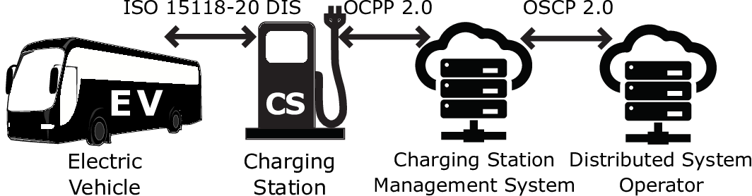
BPT-enabled EVs and CSs are essential prerequisites for bidirectional charging. Additionally, direct communication with the CSMS must support BPT. Communication to the CSs via OCPP 2.0 and to the Distributed System Operator (DSO) via Open Smart Charging Protocol (OSCP) 2.0 are particularly relevant. CHArge de MOve (CHAdeMO) and Guóbiao tujiàn Standard (GB/T) communication standards are neglected despite a large market share, as they are not part of OCPP or similar protocols. Generally the use case of depot charging is the main focus and serves as a foundation to optimize load management. Accordingly, the primary task of load management is to calculate the optimum power distribution of charge and discharge of electric buses considering the demands of the DSO.
The e-mobility ecosystem consists of a variety of interrelated actors. Figure 2 depicts the relationship among the individual actors and the available communication standards with respect to BPT.
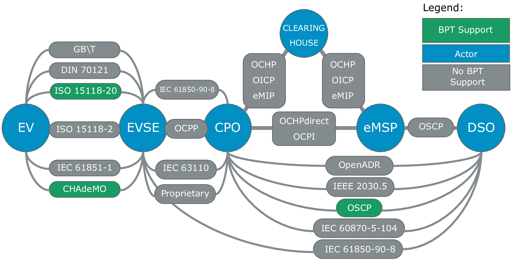
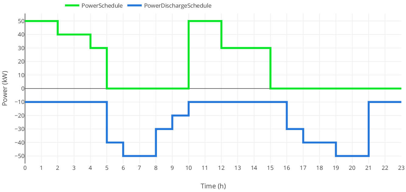
Communication between EV and Electric Vehicle Supply Equipment (EVSE) is crucial for BPT. Currently, it is only supported by the standards CHAdeMO and International Organization for Standardization (ISO) 15118-20 Draft International Standard (DIS). According to ISO 15118-20 DIS, so-called PowerSchedules and PowerDischargeSchedules can be interchanged among an EV and an EVSE before and during charging. The Figure 3 indicates the correlation between these Schedules.
Moreover, the two control modes Flexible Schedule Mode and Dynamic Control Mode are specified. The Battery Management System (BMS) of the EV can calculate its own charge or discharge curve based on these Schedules. This curve must be within the limits of the PowerSchedules and PowerDischargeSchedules. In Dynamic Control Mode the EVSE is master of the charging procedure. It dictates a PowerSchedule to the EV, leaving the EV with no other choice. The EV can inform the EVSE about its charging needs and limits before the current flows. The parameters EVTargetEnergyRequest, EVMaximumEnergyRequest, EVMinimumEnergyRequest, EVMaximumChargePower, EVMinimumChargePower, EVMaximumDischargePower and EVMinimumDischargePower are critical for BPT in load management. Figure 4 illustrates the relations of the actual EVTargetEnergy, EVMaximumEnergy and EVMinimumEnergy as well as the corresponding Requests [11]. The blue curve in Figure 4 represents the EVCurrentEnergy over time. The differences between the respective energy levels with the EVCurrentEnergy constitute the parameters EVTargetEnergyRequest, EVMaximumEnergyRequest and EVMinimumEnergyRequest.
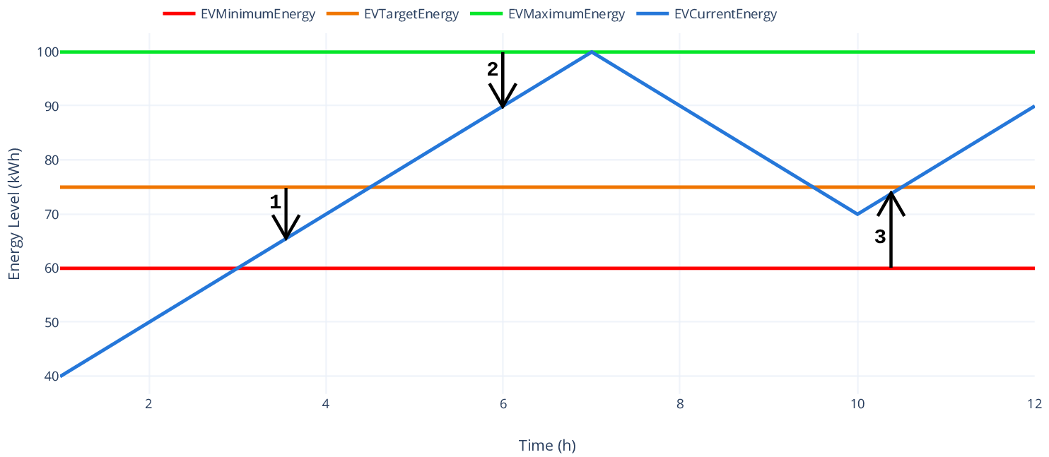
A negative EVMinimumEnergyRequest poses an unique characteristic for BPT. In this state charging only is possible. BPT is allowed only if the EVCurrentEnergy level is within EVMaximumEnergy and EVMinimumEnergy [11].
The communication between EVSE and CPO is decisive for load management. It can be implemented by International Electrotechnical Commission (IEC) 61850-90-8, OCPP, IEC 63110 or proprietary protocols, although OCPP is most common. Essentially, the tasks consist of controlling charging procedures, configuration, maintenance, payment and monitoring of EVSEs. These protocols do not support BPT currently, thus within this paper OCPP 2.0 has been extended to include BPT. The standard ISO 15118-2 is supported by OCPP 2.0 for the first time, whereby necessary adaptations are manageable [1], [3], [8], [13].
Communication between CPO and DSO enables the grid integration of load management. Especially in the context of BPT new possibilities arise. In this environment there are a number of protocols, where Open Automated Demand Response (OpenADR) 2.0 is the most common. On the other hand OSCP has been developed by Open Charge Aliance (OCA) with respect to OCPP. In general, both protocols propagate the power provided by the DSO to affect the active charging procedures managed by the CPO. In addition, the CPO can send signals to the DSO for monitoring purposes. The integration of OpenADR 2.0 with OCPP is described within a white paper published by the OCA. OpenADR 2.0 defines the so-called Virtual Top Nodes (VTNs) and Virtual End Nodes (VENs), where one VTN can represent a VEN to another VTNs. Thereby a hierarchy can be constructed. It is recommended to define the CPO as VEN in relation to the DSO or VTN. If the DSO detects an overload situation in the power grid, it triggers the messages IEvent or the events LOAD_DISPATCH and LOAD_CONTROL. The CPO translates this information into SetChargingProfile messages to be send to the CSs [2], [4], [5], [6].
The communication among the CPO and other actors allows user management and payment. This communication is important in order to achieve a user-optimized load management, i. e. to favour or penalize certain user groups. In terms of BPT and depot charging, this is less relevant.
The electro-technical fundamentals have an enormous impact both on the requirements and the functionality of load management. The most important aspects are the Kirchhoff’s circuit laws.
The first Kirchhoff’s circuit law is known under the current law and defines the behavior of the currents in a node. A node is described as a point in an electrical circuit with at least three connections to circuit elements. The current can branch at this point. The first Kirchhoff’s circuit law formulates the sum of the incoming currents to be equal to the sum of the outgoing currents in a node of an electrical circuit.
The second Kirchhoff’s circuit law known as the voltage law defines the behavior of voltages in a mesh. A mesh is described as a closed loop in an electrical circuit with at least two branches. The second Kirchhoff’s circuit law defines the sum of the partial voltages in a mesh of an electrical circuit to be zero.
Additional crucial elements are bus bars within switch gears. Switch gears are a key component of the power grid. Switch gears form the interface between feed-in and feed-out of a network node. Their bus bars represent the network nodes connecting grids of different voltage levels. A switch gear provides the actual power distribution as well as the aggregation of consumers and generators [16].
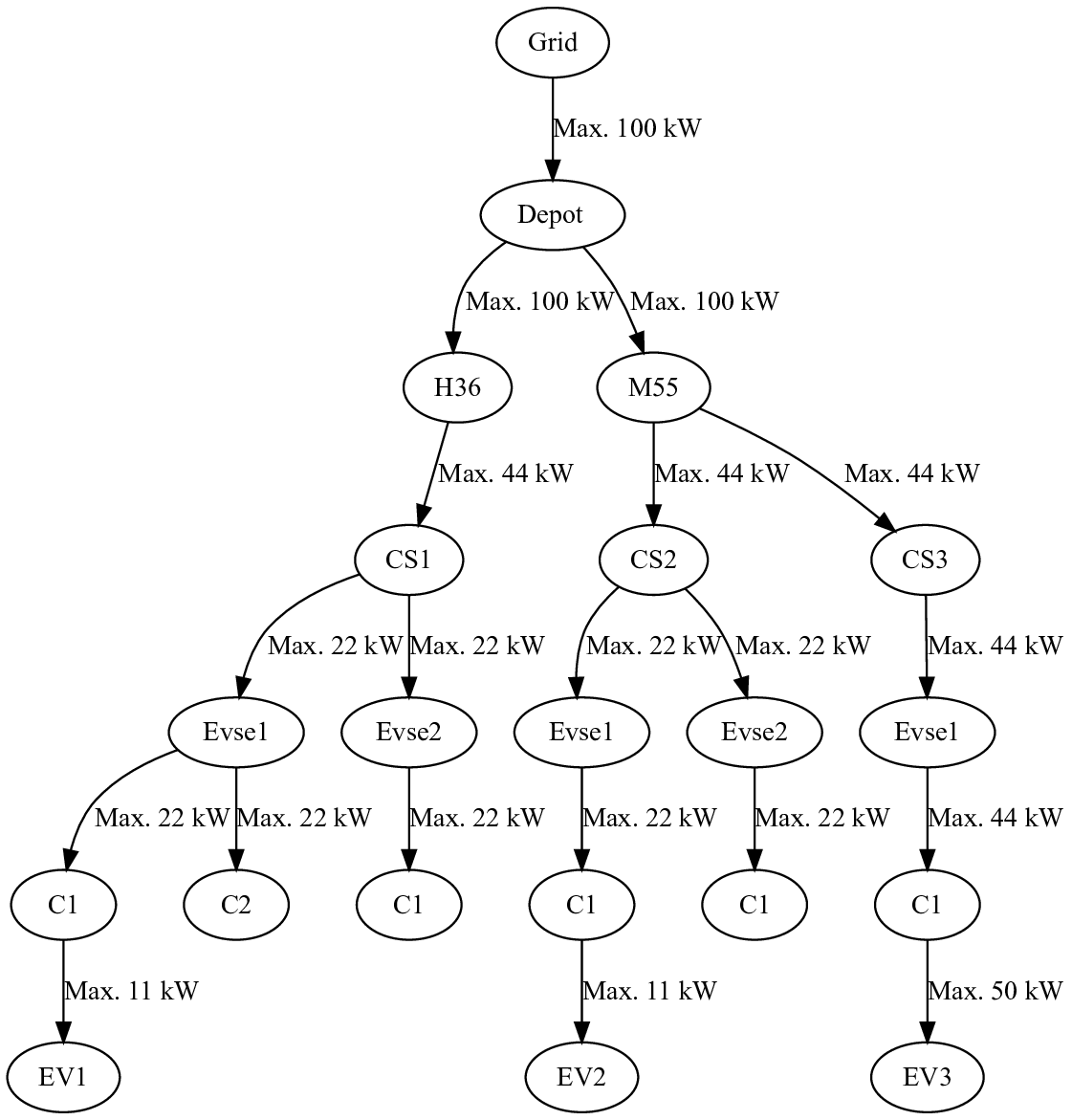
The load management of this paper has been influenced by an existing load management. However, it did not take these concepts of bus bars into account. Nevertheless, the concept of a so-called Topology was adapted and reinterpreted. A Topology abstracts the electrical circuit elements from the grid access point to the CSs and EVs. A simplified view of an example Topology with EVs is illustrated in Figure 5.
This Topology provides an abstract model for optimization. The links between the nodes in Figure 5 are displayed in one direction only.
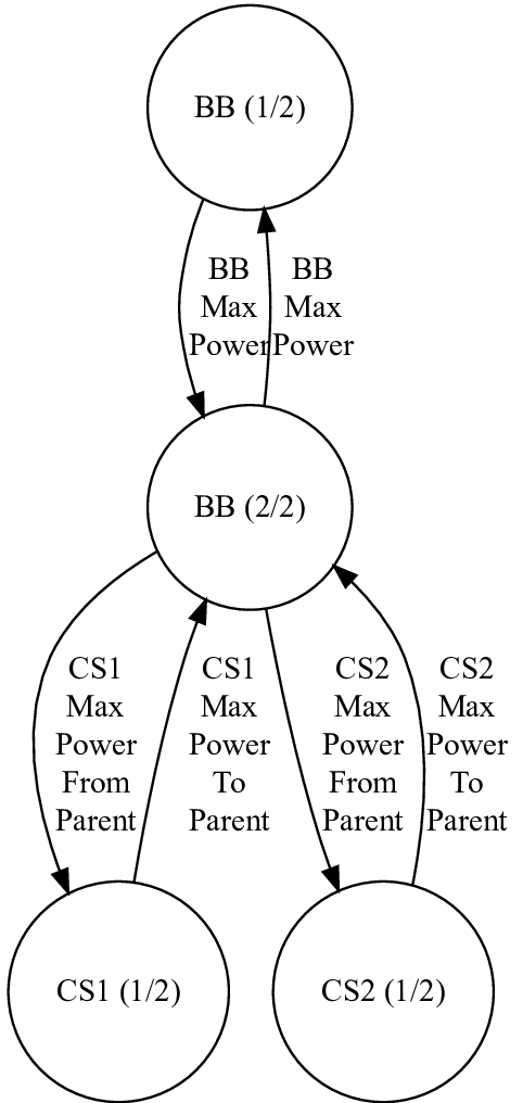
In reality there are two-way links to map the BPT. Figure 6 demonstrates a possible model of a bus bar (BB).
In order to improve the existing load management, the issue is reconsidered upon the integration of BPT. This can be mathematically formulated as Maximum Flow Problem. The Maximum Flow Problem can be modelled on a digraph whose edges contain maximum flow capacities between nodes.
The objective of the Maximum Flow Problem is to propagate a maximum flow within this digraph from a source s to a sink t. Figure 7 illustrates such a digraph.
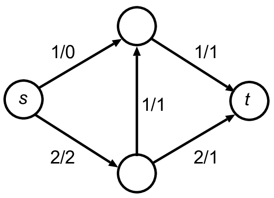
The mathematical assignment of flow is affected by the so-called Capacity Constraints and Flow Conversation Constraints. Capacity Constraints are formulated as inequalities. They define the capacity for each edge of the digraph. Flow Conversation Constraints are equations defining the flow rate for each node except the source and sink. The sum of the flow values leading to a node must be equal to the sum of the flow values leaving that node. By means of these Flow Conversation Constraints the first Kirchhoff’s circuit law is fulfilled.
To solve the Maximum Flow Problem different methods exist, which include the Linear Optimization, the Dinic’s Algorithm and the Ford-Fulkerson Algorithm. This paper focuses on Linear Optimization.

The vector x represents the variables to be determined. The vectors c and b and the matrix A define known coefficients. The objective function cTx is maximized with respect to the conditions Ax = b and x = 0. The solution set of this linear objective function resembles a convex polytope or simplex [17].
The extension of OCPP 2.0 for BPT is the prerequisite for the integration of BPTs into load management. The messages NotifyEVChargingNeedsRequest, NotifyCentralChargingNeedsRequest and NotifyEVChargingScheduleRequest were altered and enhanced to exchange the essential BPT specific parameters among CS and CPO.
The message NotifyEVChargingNeedsRequest was extended by the EV parameters mentioned in section II, such as EvMaximumEnergyRequest and EvMaximumDischargePower. Utilizing the extensions to the message NotifyCentralChargingNeedsRequest, load management can communicate the Control Mode and one or more charging profiles for charging and discharging including price information to EV via CS. In the context of the extended message NotifyEVChargingScheduleRequest the EV informs the load management not only about the charging profile being used, but also about it’s Control Mode.
After achieving the foundation via this protocol extension, a generator for load management test scenarios was created. The generator allows to create Topologys of any complexity and number of charging procedures. BPT specific parameters relevant to load management, such as the maximum charge or discharge power of the EVs or charging stations or the desired energy amount at departure can be generated using configurable distribution functions.
By means of these generated test scenarios the strategies Priority-, Equal- and Planning-Strategy for load management developed in this paper were evaluated.
A Strategy calculates the power distribution of all active charging processes of a Topology for a certain time frame. The result of a Strategy is indicated by two lists. The first list represents the execution priority. The second list embodies the percentage of available maximum power. The charging process with the highest execution priority is processed first. The power is assigned using the percentage of the maximum power. A percentage of the maximum charging power of 100% with the highest execution priority results in the maximum charging power for this charging process in this period. A percentage of the maximum charge power of 0% with the highest execution priority results in no power in that period. Similarly, a negative percentage of the maximum discharge power will provide the corresponding discharge power for this period.
The Equal-Strategy is the simplest Strategy. It realizes an equal distribution of the power over all active charging processes. The Equal-Strategy always provides the same execution priority and a maximum power percentage of 100%. This Strategy can be extended by reducing all maximum power percentages by 100%. This reduction can be used to control the total power consumption, thus responding to current price fluctuations and grid situations. In addition, aggregation of charging processes is possible, with each group having a different percentage of maximum power. The charging processes in a group have the same maximum power percentage.
The Priority-Strategy is primarily based on execution priorities. Any external dependencies can be mapped to the power distribution, in particular existing planning and scheduling systems. Analogous to the Equal-Strategy it may be expanded, by altering the percentage maximum power. In general, the Priority-Strategy and Equal-Strategy can be mapped to each other. The grouping of the Equal-Strategy allows different percentage maximum power levels to be defined. The smaller the groups, the greater the similarity between Equal-Strategy and Priority-Strategy. The reverse is also true.
According to its name, the Planning-Strategy assigns power based on a pre-calculated plan. This plan represents a time-discrete power assignment of parallel charging processes of a Topology. The plan is calculated consisting of a two-step procedure using Linear Optimization.
In the first step, the objective function is formulated in a way that the energy charged at the beginning of the charging processes is maximized. Negative energy amounts corresponding to discharging are excluded in this step by means of constraints. In addition, further constraints ensure that the charging and discharging limits of the Topology, EVs and the charging power already assigned and the EVMaximumEnergyRequest and EVTargetEnergyRequest are not exceeded. On the basis of this result the required partial energy amounts are determined, which are necessary to reach the EVMinimumEnergy of the charging processes with positive EVMinimumEnergyRequest. In the next step, the partial energy amounts of the discrete time steps are marked as constant until the EVMinimumEnergy is reached. This prevents discharge before the EVMinimumEnergy is reached.
The second Linear Optimization thus calculates the partial energy amounts additionally charged and discharged in favor of others EVs.
The optimization of this planning offers numerous degrees of freedom, such as the factors of the objective function, the constraints or the number of variables. The factors of the objective function are crucial due to maximizing or minimizing the energy amounts to be assigned to the charging processes as well as the partial amounts of energy to be controlled within them.
For each charging process the desired power curve is adjustable, thus flat or steep power gradients are possible. Different criteria for prioritizing energy amounts of the charging processes can be used. The start or end time as well as the duration of the charging processes are possible criteria.
A higher resolution of the charging processes by means of additional time-discrete steps results in more variables. On the one hand, this increases the problem complexity and the number of possible factors of the objective function. On the other hand, the power distribution of charging processes is controlled more precisely over time. Depending on the application, constraints can be added or removed. Another factor is the planning scope. The uncertainty of the forecasts and the number of variables increases with it, which adds to the problem complexity and decreases the quality of the results.
The planning allows to consider a day-ahead price forecast of the European Energy Exchange (EEX). In contrast to the Equal-Strategy and the Priority-Strategy, planning allows to react to future price fluctuations, by modeling them by means of the factors of the objective function.
The key results are presented in the Figures 9, 10 and 11. They illustrate the calculated charging profiles of the Strategies based on a generated test scenario with twelve EVSEs divided among ten charging stations. The Figures 8 and 9 display two possible charging profiles referring to one charging process of a EV.
The sample EV is capable of charging for 11.1 hours and has a maximum charging power of 150 kilowatts (kW). Charging power is limited to 140 kW due to the Topology. The EV is capable of BPT with a maximum discharge power of 80 kW, it can charge a maximum energy of 534 kilowatt hours (kWh) and requires a total energy of 324 kWh at departure time.
The Figure 8 depicts a charging profile for this EV based on the Priority-Strategy. This assigns the EV the maximum power until the desired energy amount is reached based on the priority. In comparison, the Figure 9 depicts a charging profile for this EV, which was calculated using the Planning-Strategy.
In this case, the EV is charged up to the maximum energy amount first, which allows discharging later. Thus another EV will receive additional power and will complete charging earlier. After all, only sufficient energy is discharged until the desired energy amount is reached at departure time.
The impact of this additional energy increases significantly in sum. The Topology has a maximum power of 300 kW enabling nine EVs to charge or discharge simultaneously. Analogous to the charging profile in figure 8, each incoming EV is assigned the maximum power until the desired energy amount is reached. In Figure 10 the maximum power consumption of the Topology exceeds starting from the eighth hour after charging the first EV. This is due to too large power assignments of the EVs.
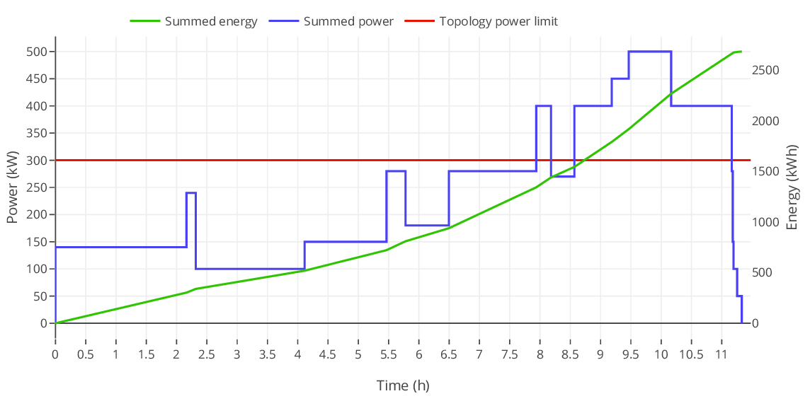
The Figure 11 illustrates the accumulated charging profiles and charged energy of the identical Topology using the load management with the Planning-Strategy.
The maximum power consumption of the Topology of 300 kW is reached, but never exceeded. The power curve fluctuates less and yet the same total energy amount is reached due to BPT.
IV. Discussion and future work
This section provides a summary and discusses comparable load managements with respect to the load management of this paper. Subsequently, an outline of future work is presented.
The developed approach and the realization emphasize the fundamental feasibility and optimization of load management by means of the support of BPT. The results not only indicate that significant optimizations can be achieved within a load management system using BPTs, but that the necessary requirements can be conceptually combined with OCPP 2.0.
The results of the standardization of the e-mobility ecosystem reveal a large number of actors involved as well as a high degree of complexity in supporting BPT for load management. As a consequence, the electro-technical fundamentals, the protocol procedures and the optimization methods play a decisive role. The extension of OCPP 2.0 is a prerequisite for the feasibility of load management including the support of BPT. Based on these findings, the special characteristics regarding the use of depot charging are formulated. In addition, the standardization has not yet been completed, new technologies are opening up further opportunities and further research work is ongoing. Due to this uncertainty, the solution presented in this paper is deliberately flexible. The development of suitable extensions for OCPP 2.0 as well as optimization strategies have been developed in the meantime.
The implementation confirms the feasibility of the software design, the strategies and the extension of the OCPP. The results underline the potential of BPT in load management for the use case of depot charging. In addition, the relevance of planning ahead in load management is emphasized.
The load management developed by Detzler is based on the evolutionary algorithm. Test scenarios with varying numbers are examined. The evolutionary algorithm, consisting of recombination, selection and mutation, is applied in the following form. First a starting population of random individuals is generated. An individual represents a sequence of charging processes including power assignments for a certain period of time. Minima and maxima of the EV ensure that the assigned charging power of an individual is always within a valid value range. The evaluation of individuals is based on a cost function involving all EVs and the energy price. The recombination process depicted in Figure 12 begins by selecting two parent individuals of the current generation. A random cross-over point is selected, which is associated with a particular charging process in the sequence of the charging processes. The child individuals are created by dividing the parent individuals at the cross-over point and assembling each one with the complementary part of the other parent individual. The mutation distinguishes between three variants, changing only the order of particular charging processes, the charging power or both [9].
In the test scenarios of Detzler it was found that the fitness value of the algorithm converges after 100 generations. In addition, charging profiles for 200 vehicles at 100 generations could be calculated within 14 seconds [9].
Due to randomness, the runtime of the evolutionary algorithm is not deterministic. The memory consumption is constant, because the number of individuals remains constant over time. However, nonlinear constraints can be mapped.
 Figure 12. Recombination of two individuums (Source: [9])
The use case of BPT is not considered, so a direct comparison is not possible. In addition, Topology conditions are modelled by means of a valid value range. The Topology conditions of this paper provide dependencies between the assigned EV powers. This increases the complexity during the creation of valid individuals, thus also increasing runtime.
Basically, the approach of Detzler is similarly promising as the one presented in this paper. However, only a direct comparison, examined in future work, provides certainty. The realization of this comparison can be done with an own Strategy based on the evolutionary algorithm.
The load management of Lee, Chang, Jin, et al. relies on an infrastructure consisting of a 50 kW Direct Current (DC) Fast Charger, consumers from a garage as well as its own three-phase alternating current transformer to which 54 type-2 EVSEs of 6.6 kW are subordinated. The load management procedure is an online scheduling procedure and requires discrete time steps. In addition, the amount of available EVs, the amount of active EVs and a EV state must be defined. The state of the EVs is represented by a tuple consisting of the requested energy amount, the remaining charging time, the maximum power of the EVs and a metering of the charged energy amount until the current time. Based on this data, the algorithm is performed in the following three steps:
- The amount of active EVs is determined using the plugged EVs with a remaining energy demand greater than zero.
- It is checked whether a new schedule has to be calculated, which can be triggered by events or a timeout.
- A new optimal schedule is calculated by maximizing an objective function using an optimization horizon.
The optimization horizon represents the constraints. The procedure is iterative, meaning that the state parameters for the next point in time are recalculated for each point in time for each EV. The objective function is determined by operator objectives in the form of regularization and weighting factors. This optimization offers various options. Charging according to a certain curve, e.g. the generation of renewable energies, the smoothing of the charging curve by minimizing the amount between the partial powers as well as fastest possible or evenly distributed charging are enabled. In addition, auxiliary conditions are defined which ensure that the charging power between a value of zero and the EV maximum power, the energy amount charged, the power limits of the infrastructure and the prevention of charging processes after departure time are ensured. Furthermore, Lee, Chang, Jin, et al. define so-called Second Order Cone conditions that utilize specific properties of the three-phase AC transformer. The Second Order Cone conditions improve the phase imbalance in the three-phase grid. Moreover, non-ideal charging behavior is counteracted by increasing the calculation frequency [12].
The iterative procedure is similar to the one presented in this paper. It differs in its absence of planning.. On the one hand, this results in the advantage of reduced complexity, as the calculations need to cover a short period of time. On the other hand, planned changes are difficult to consider.
The primary concern in the project by Projektplaner LEW is on use of locally produced Photovoltaic (PV) power for charging of electric vehicles. The BPT is thus represented by the PV system. The intended fields of application are fleets and car parks. In the project eight Alternating Current (AC)-CSs with two charge points of 22 kW each were installed, thus having an aggregated maximum power of 352 kW. The aggregated maximum power was limited to 100 kW by the load management. 78 % of the EVs had a standing duration between 8 and 14 hours.
The load management calculates the charging profiles using Linear Optimization based on a cost function depending on the EEX electricity prices and the PV energy, taking into account the minimum and maximum power of the EVs. By means of an additional uncertainty factor it is ensured that the EVs are fully charged even with earlier departure. An underestimation of the actual charge duration compensates for the modelling error of a permanently constant power. Due to the charging characteristics of lithium-ion batteries, a permanently constant power is not feasible. The project involved 56 volunteers over a period of two years. During the test phase, various findings were obtained. This includes the fact that not all EVs support the ISO 15118-2, some EVs switch off at too low power and the creation of the charging profiles took longer than three minutes and thus too long. The use of PV energy was increased by more than 40 % [15], [7].
This load management does not consider Topology conditions. In addition, the problem of skew load is not addressed. One option to counteract this is the use of OCPP in combination with charging stations, enabling to select the phase to be used. Possibly a skew load was counteracted during installation by rotating phase assignment of the charging stations to the grid. In this way, if the charging stations are used uniformly, all phases are balanced. A lesson of considering a minimum output power can be derived from this.
The paper by Wolpert and Macready proves the proposition that a universal method for solving an optimization problem does not exist considering the set of all problems. This proposition is presented in the form of the following two theorems.
The average performance of two algorithms for a set of optimization problems is independent of the algorithm selected. |
Finally, it should be noted that load management with the support of BPT holds enormous potential for a variety of applications, especially for depot charging. Furthermore, a successful integration into the existing e-mobility ecosystem is possible despite high complexity. Currently there is an uncertainty of the standardization, due to ongoing development of the standard ISO 15118-20 DIS and additional factors, such as the integration of other protocols like CHAdeMO or Deutsches Institut für Normung eV (DIN) 70121. The developed software design as well as the prototypical implementation thus have a high adaptability for potential changes of the standardizations. The intention in ISO 15118-20 to introduce an additional data type for the charging profiles in Dynamic Control Mode is an example of such a current new feature.
Presently, this solution provides promising results for the use case of depot charging. In particular, the BPT represents a valuable enhancement in terms of optimization compared to other load management systems. In future the extension of the generator for test scenarios is conceivable, in order to produce further use cases and detailed sample data. Additional strategies can be developed and existing ones can be optimized. By means of a simulation these can be validated in the long term. Moreover, they can be employed in a future collaboration with a DSO in order to gain practical insights.
[1] Alliance, Open Charge. 2015a. Open Charge Point Protocol 2.0: Part 2 – Specification. Open Charge Alliance.
[2] ———. 2015b. Open Smart Charging Protocol 1.0 – Interface Description Between Dso and Central System. Open Charge Alliance.
[3] ———. 2017. Open Charge Point Protocol 1.5. Open Charge Alliance.
[4] ———. 2019. Open Smart Charging Protocol 2.0 – Specification Draft Use Case Proposal. Open Charge Alliance.
[5] Alliance, OpenADR. 2012. OpenADR 2.0 Profile Specification A Profile. OpenADR Alliance.
[6] ———. 2015. OpenADR 2.0 Profile Specification B Profile. OpenADR Alliance.
[7] Carron, Virgile. 2014. Untersuchung Geeigneter Optimierungsstrategien Zur Umsetzung Eines Intelligenten Lademanagements Für Elektrofahrzeuge. Hochschule für angewandte Wissenschaften München.
[8] Commission, International Electrotechnical. 2016. Technical Report 61850-90-8: Communication Networks and Systems for Power Utility Automation – Part 90-8: Object Model for E-Mobility. International Electrotechnical Commission.
[9] Detzler, Sarah Katharina. 2017. “Lademanagement Für Elektrofahrzeuge.” PhD thesis, Karlsruher Institut für Technologie (KIT); KIT Scientific Publishing, Karlsruhe. doi:10.5445/KSP/1000057827.
[10] IEA. 2019. Global Ev Outlook 2019. IEA.
[11] ISO/IEC. 2018. “ISO/IEC DIS 15118-20: Road vehicles – Vehicle to grid communication interface – Part 2: Network and application protocol requirements.”
[12] Lee, Z. J., D. Chang, C. Jin, G. S. Lee, R. Lee, T. Lee, and S. H. Low. 2018. “Large-Scale Adaptive Electric Vehicle Charging.” In 2018 Ieee Global Conference on Signal and Information Processing (Globalsip), 863–64. doi:10.1109/GlobalSIP.2018.8646472.
[13] Mültin, Dr. Marc. 2017. IEC 63110 – Standardizing the Management of Electric Vehicle (Dis-)Charging Infrastructures. V2G Clarity.
[14] Poon, Linda. 2019. Why U.s. Cities Aren’t Using More Electric Buses. Citylab.
[15] Projektplaner LEW, LVN und FfE. 2017. Lademanagement an Park and Ride Parkplätzen. Innovations- und Technologiezentrum.
[16] Schwab, Adolf J. 2009. Elektroenergiesysteme – Erzeugung, Transport, übertragung Und Verteilung Elektrischer Energie. 2. Aufl. Berlin Heidelberg New York: Springer-Verlag.
[17] Suhl, Leena, and Taïeb Mellouli. 2013. “2 Lineare Optimierungsmodelle.” In Optimierungssysteme: Modelle, Verfahren, Software, Anwendungen, 31–76. Berlin, Heidelberg: Springer Berlin Heidelberg. doi:10.1007/978-3-642-38937-5_3.
[18] Wolpert, D. H., and W. G. Macready. 1997. “No Free Lunch Theorems for Optimization.” Trans. Evol. Comp 1 (1). Piscataway, NJ, USA: IEEE Press: 67–82. doi:10.1109/4235.585893.
by
Benjamin Kowatsch
Leave a Reply
You must be logged in to post a comment.